PRODUCT DETAILS
Item specifics
- Weight:
- Size:
Product Description
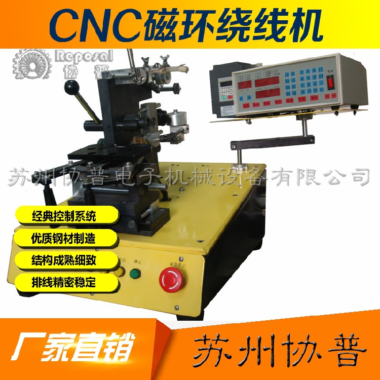
SP-D102 winding machine standard configuration:
- Axis: Single axis
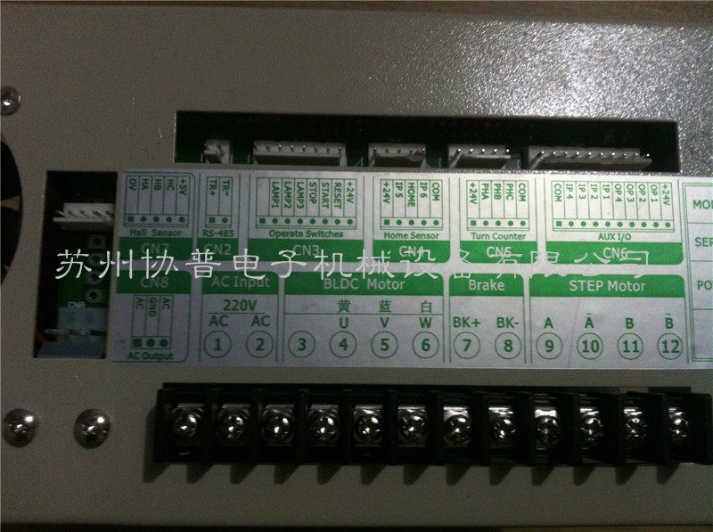
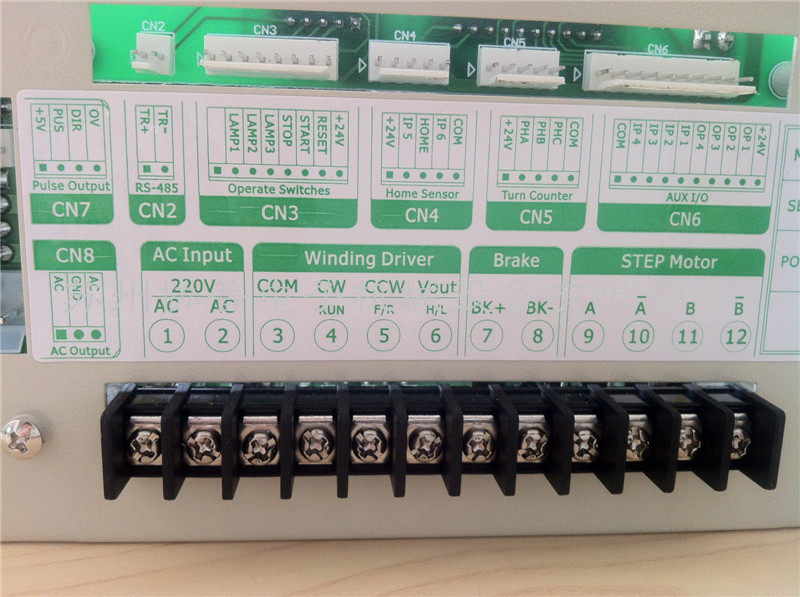
- Motor: Brushless DC
- Cable motor: 57 stepper motor
- Maximum speed: 6000
- Power Supply: AC220 or AC110V
- Frequency: 50/60HZ
- Applicable wire diameter: 0.04-1.2
- The largest width: 108MM
- Number of memory groups: 999 groups
- Maximum rotation diameter: 200MM
- Machine weight: 40KG after packaging
- Machine net size: 320*340*400
- Fitting size:550*480*530
Standard accessories:
Foot switch
Set of hex wrenches
A power cord
A copy of the manual
A set of crossovers
Set of tape table
Line head set.
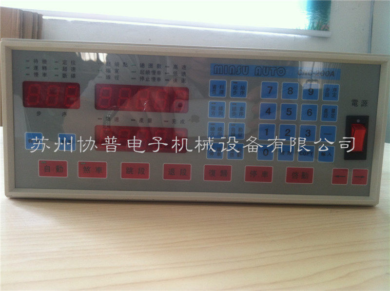
CNC automatic cable winding machine controller introduction
Step key
- <Step setting>: Used to enter the data setting state.
- <Start Step>: Used to set the memory to start positioning.
- <End Step>: Used to set the end point of the memory.
Yield key
<Production setting>: Used to set the target output.
number key
<0>...<9>: A total of ten keys are used to input numerical values, < "0" key, high speed operation in winding machine for high and low speed switching>.
Display switch button
- <Speed>: The speed "RPM" and the output display are switched.
- <Return to zero>: The output counter is cleared to zero.
Function key
- <Auto>: Auto/Do not switch automatically.
- <Brake>: When parking, the bobbin brakes or relaxes.
- <jumping segment>: When the winding is paused, skip to the next position.
- <Retraction>: When the winding is paused, jump to the previous position.
- <Reset>: In any state, the current operation is terminated and returned to the standby state.
- <Parking>: When the winding is completed, the current operating procedures are suspended.
- <Startup>: Start the winding action.
Data key
- <Data Selection>: Used to select a data item when editing.
- <Line direction>: Used to set the direction of the line in the inner or outer line when editing the cable.
- <Rolling direction>: Used to set the clockwise or counterclockwise direction of the winding of the bobbin during editing.
- <Parking at both ends>: When editing, it is used to set whether the cable bar is to be stopped at both ends of the bobbin.
- <Auto homing>: When editing, it is used to set whether the cable lever is automatically displaced to the winding position of the next product.
- <Auto Start>: When editing, it is used to set whether to automatically start the second product after completing a product.
- <Alternative>: It is mainly used to set the direction of the cable, the direction of the winding, stop at both ends, automatically return to the position, and automatically start.
- 〈←〉: When editing, use to move the cable lever to the left to set the winding point.
- 〈→〉: When editing, use to move the cable lever to the right and set the winding point.
Data display light
- <Starting point>: The starting position of the cable rod. This position is the distance calculated from the origin of the cable rod.
- <Width>: When the copper wire is wound around the skeleton (bobbin), the skeleton needs to be wound.
- <Line diameter>: diameter of copper wire (need to calculate the thickness of the lacquer bag), the setting range is 0-9.999mm.
- <Total number of turns>: Number of turns required for winding, setting range 0-99999.9 laps or 0-99999 laps.
- <Winning and jogging>: In order to prevent the phenomenon of slipping, disconnection, etc. due to high speed during winding, the number of turns of slow winding after starting is set to 0-999.9 laps.
- <Stop Slow>: To prevent the phenomenon of slipping, disconnection and counting inaccuracy due to high speed when stopping winding, the number of turns of slow winding after high speed to low speed before the number of windings is completed. The range is 0-999.9 laps.
- <High speed>: The speed (rpm) at high speed winding, which is displayed as the percentage of the maximum speed on the display, and the setting range is 10%-99%.
- <Low speed>: The speed (rpm) at low speed winding, the display shows the percentage of the maximum speed, the setting range is 6-10%. “If the low speed is too low, the device cannot start.
Status display light
- Standby: Lights up—indicating standby, lights are off—indicating winding or editing.
- Operation: Lights up—indicating that the winding is in the light, the light is not lit—indicating that it is stopped.
- Slow: The light is on—it indicates that the wire is being wound at a low speed, and the light is not lit—it indicates that the wire is being wound at a high speed.
- Positioning: Lights on—Indicating that the cable rod is positioned as a wrap or returned to the origin.
- Overspeed: The light is on—the winding speed is too fast, and the cable bar is out of sync with the bobbin.
- Connection: Lights up - indicates that the network communication is busy.
- Speed: Lights up—Indicates the speed displayed on the current Output/Speed display.
- Yield: Lights up—represents the current display of the Yield/Speed display.
- Finish: Lights on - indicating that the production quantity has reached the production target
The above is the price of an entire CNC-200A winding machine.
You can also purchase the following products according to your needs.
Electromagnetic clutch:
Winding machine brakes Brake pads Electromagnetic brakes Electromagnetic clutch Brake pads for winding machines
Model: FB-06
Power: 11W
Voltage 24V
It is mainly used for winding machines with high requirements on the number of turns.
Winding machine electromagnetic brake
Electromagnetic brake A mechanical part that stops or decelerates moving parts in a machine. Commonly known as brakes, brakes. The electromagnetic brake is mainly composed of a brake frame, a brake member and an operating device. Some electromagnetic brakes are also equipped with automatic adjustment of the brake gap. In order to reduce the braking torque and structural size, electromagnetic brakes are usually installed on the high-speed shaft of the equipment, but large equipment (such as mine hoists, elevators, etc.) with high safety requirements should be installed close to the working part of the equipment. On the low speed shaft.
basic introduction:
Some electromagnetic brakes have been standardized and serialized and are manufactured by professional factories.
Electromagnetic brakes are an ideal automatic actuator in modern industry. They mainly play the role of transmitting power and controlling motion in mechanical transmission systems. The utility model has the advantages of compact structure, simple operation, sensitive response, long service life, reliable use, and easy realization of long-distance control.
It is mainly matched with series motors. Widely used in metallurgy, construction, chemical, food, machine tools, stage, elevators, ships, packaging and other machinery, and in the case of power failure (anti-risk) braking and other occasions.
The resistance torque that must be applied to stop or decelerate the mechanical running component is called the braking torque. The braking torque is the basis for the design and selection of the brakes. The size is determined by the type and working requirements of the machine. The performance of the friction material (brake) used on the brake directly affects the braking process, and the main factors affecting its performance are the operating temperature and temperature rise. The friction material should have a high and stable coefficient of friction and good wear resistance. Friction materials are classified into metal and non-metal. The former is commonly used in cast iron, steel, bronze and powder metallurgy friction materials, the latter including leather, rubber, wood and asbestos.
Types of:
The brakes that use the electromagnetic effect to achieve braking are divided into electromagnetic powder brakes and electromagnetic eddy current brakes, electromagnetic friction brakes and other forms.
- Electromagnetic powder brake: When the excitation coil is energized, a magnetic field is formed. The magnetic powder is magnetized under the action of a magnetic field to form a magnetic powder chain, and is polymerized between the fixed magnetizer and the rotor, and the braking force is achieved by the bonding force and friction force of the magnetic powder. When the excitation current disappears, the magnetic powder is in a freely loose state, and the braking action is released. The brake is small in size, light in weight, small in excitation power, and the braking torque is independent of the rotational speed of the rotating member, but the magnetic powder causes wear of the parts. It is easy to control automatically and is suitable for drive systems of various machines.
- Electromagnetic eddy current brake: A magnetic field is formed when the excitation coil is energized. The armature on the brake shaft rotates to cut the magnetic lines of force to create eddy currents. The eddy currents in the armature interact with the magnetic field to form a braking torque. Electromagnetic eddy current brakes are rugged, easy to maintain, and have a wide range of speed regulation; however, at low speeds, the efficiency is low and the temperature is raised, and heat dissipation measures must be taken. This type of brake is often used in machines with vertical loads.
- electromagnetic friction brake: the excitation coil energizes to generate a magnetic field, through the yoke to attract the armature, the armature through the coupling to achieve braking.
In addition, it is also subdivided into dry single-chip electromagnetic brake dry multi-plate electromagnetic brake wet multi-plate electromagnetic brake and so on.
There are also braking methods that can be divided into energized brakes and power-off brakes.
The electromagnetic brake is a connector that transmits the active side torque to the passive side. It can be freely combined, cut off or braked according to the need. It is operated by electromagnetic force, called electromagnetic clutch, brake, and has response speed. Fast, simple structure and so on.
Electromagnetic brake function:
The electromagnetic brake is a device that stops the machine and stops in a short time; the brake can also be used to reduce or adjust the speed of the machine in a short period of time.
Optional elements:
Due to the braking and fixing of the rotating body, the stator portion should be securely fixed to the stationary portion. Moreover, there are several methods for the armature unit of the electromagnetic brake to be mounted on the rotating body, and it is necessary to select a model that is suitable for the shape of the mounting portion. In addition, the electromagnetic brake is also equipped with an integrated structure, which does not require a gap adjustment model.
Precautions:
1, on the shaft to be braked, because the shaft is usually braked, how to effectively mount to the shaft is the focus of selection.
2. It can also be directly mounted on the rotating body. For the inertial body that is not fixed to the shaft, even if the shaft is braked, it cannot be stopped, so it should be directly mounted on the rotating body.
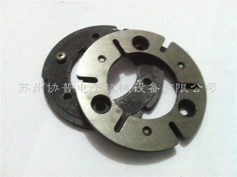
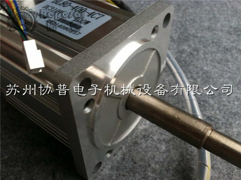
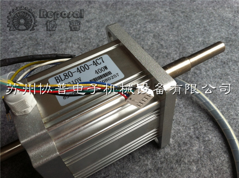
Standard Accessories DC400W Brushless DC Motor,No electromagnetic clutch
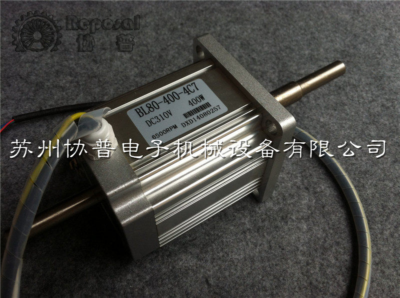
DC400W+ DC brushless electromagnetic clutch

Accessories that can be purchased separately: Winder controller
Electromagnetic brake:
Winding machine accessories Winding machine tensioner Tensioner Magnetic tensioner (vertical)
Magnetic tensioner product operation
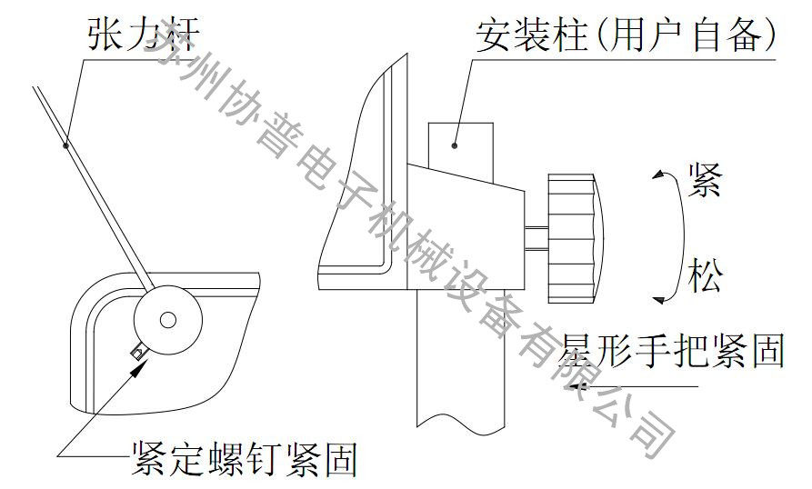
1. Install the tensioner: Fix the tensioner, install the tension bar as shown and lock the fixing screw. When locking, the screw must be aligned with the plane of the shaft.
2, adjust the wool ring clip: through the wool ring knob on the back of the tensioner to adjust, loosen the degree of clamping of the wool collar, right-handed is tight, left-handed is loose. When using a small tension, the degree of clamping of the wool collar is such that the enameled wire does not fall out of the wool loop, so that it only produces a slight resistance.
3. Set the output tension: According to the user's required tension, by repeatedly adjusting the tension adjustment dial and the back tension knob, the output tension can be achieved and the working angle of the tension rod is suitable.
Tension and back tension adjustment instructions:
1. Tension adjustment method:
Change the output tension by rotating the tension adjustment knob. If the tension is small, adjust the tension by the right-hand tension adjustment knob; if the tension is large, the left-hand tension adjustment dial reduces the tension.
Note: When the left-hand (reduced tension) tension adjustment knob must be adjusted when the tensioner stops working, otherwise it will cause wire breakage and tension instability.
2. Anti-tension adjustment method:
When the angle of the tension bar swings in normal winding is the best working state when it is parallel to the plane on the box body (as shown in the figure below), if the tension bar is higher than the parallel position, the back tension knob needs to rotate in the “low” direction (right-handed), otherwise Then you need to rotate in the "high" direction (left-handed).
Tensioner selection model table
model
|
Reference Use Wire diameter Range
|
Tension range
|
MT-00
|
0.02~0.08MM
|
4~40g
|
MT-01
|
0.04~0.12MM
|
10~120g
|
MT-02
|
0.06~0·18MM
|
25~200g
|
MT-04
|
0.08~0.25MM
|
50~400g
|
MT-06
|
0.12~0.35MM
|
80~600g
|
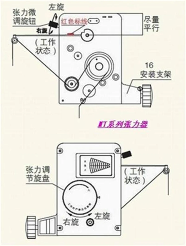

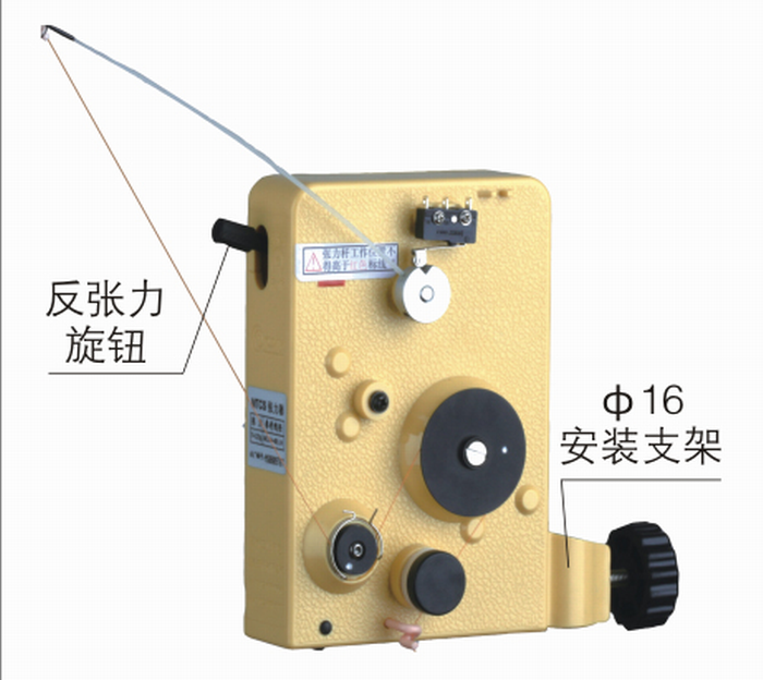
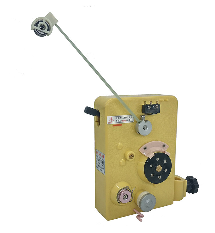
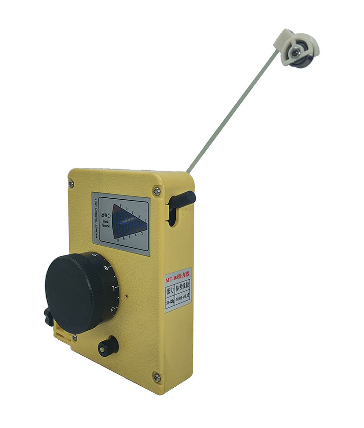
Schematic diagram of the shape of the tensioner (mechanical)
Note: The structural differences caused by different models are subject to the actual product.
Tensioner use environment requirements:
- Temperature requirement: -5°C~30°C
- Humidity requirement: 30%~60%
- Air purification requirements: Air cleanliness level is 6 (1000).
- Enamelled wire cleaning requirements: The enameled wire should be stored in a relatively clean environment. The enameled wire should be clean and the surface should be clean and free of dust. If a waxed enameled wire must be used, the user should add a multi-stage filter and clean the wire. In order to prevent dust from being mixed with the wax layer, it is attracted to the damper ring to cause malfunction.
Star Handle Fasten the mounting post (user-supplied), tighten the tension bar and tighten the tension bar.
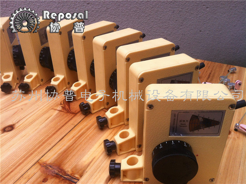
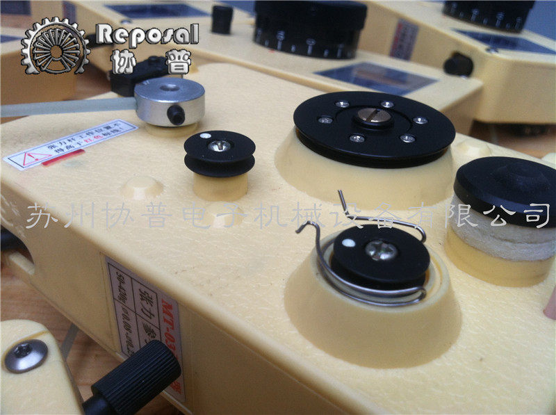
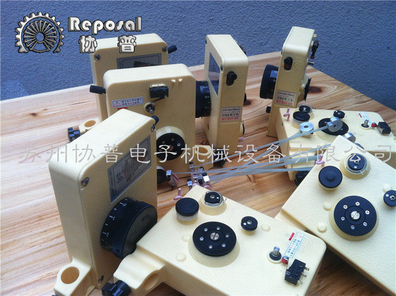
Tensioner installation instructions (Install the tension bar and the fixed tensioner as shown in Figure 2.)

Tension adjustment steps:
- The enameled wire passes through the tensioner as shown in the product label.
- The degree of clamping of the wool collar is relaxed by adjusting the two knobs on the back of the tensioner. When using a tension below 5g, the wool collar must be completely relaxed, giving it only a small amount of resistance.
- According to the user's required tension, by repeatedly adjusting the tension adjustment knob and the tension fine adjustment knob, the output tension is required and the working angle of the tension rod is appropriate. (See Figure 3)
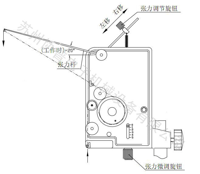
The tension adjustment method is shown in the table below.
Tension situation
|
Tension bar working angle
|
Adjustment method
|
Too much tension/small
|
bottom tension fine adjustment knob left/right
|
Tension bar working angle is large / small Top tension adjustment knob is moved left / right
|
Small tension
|
large working angle of tension bar
|
bottom tension fine adjustment knob right hand
|
the working angle of the tension bar is small
|
the top tension adjustment knob is shifted to the right
| |
Large tension
|
the working angle of the tension bar is large
|
the top tension adjustment knob is shifted to the left
|
the working angle of the tension bar is small
|
the bottom tension fine adjustment knob is left-handed
| |
Under normal circumstances, when the tension bar angle is about 20°, it is the best working condition, and the working angle can also be used according to the user's needs.
| ||
note:
- At the end of the adjustment, the working angle of the tension bar is the same as the angle when the static is installed, or the tension bar is horizontal when it is turned on. Please re-adjust the tension to avoid abnormal wear of the components of the tensioner. And reduce the service life.
- When the tensioner is in normal use, please check whether there is any residual enameled wire breakage on the damper wheel when replacing the enamel wire, so as to avoid the irregular tension change caused by being caught in the damper wheel when the machine is turned on again.
- If the tension adjustment is still invalid, please confirm whether the selected model is correct, or contact our company in time.
Common faults and solutions:
No. Fault phenomenon Remedy
- After a period of use, the tension becomes smaller. The tension adjustment knob turns to the right.
- Jump the line outside the damper wheel or the line to the damper wheel. Relax the wool ring properly.
- Damping wheel slips during operation. Appropriate clamping of the wool ring
Repair instructions:
1, normal use, no customer repair, free warranty for three months from the date of purchase.
2, beyond the warranty period, provide a fee for repair service for life.
3, Even during the free warranty period, the user will be responsible for the maintenance costs in the following cases:
a). Replace consumables: woollen ring, guide porcelain, wire wheel, tension bar;
b). Damage caused by improper use or force majeure;
c). Disassembled without the permission of the company;
d). Model is not applicable, damage caused by over-range use;
e). The above is quite a type of situation.
packing list:
- packing list:
- Tensioner *1PCS
- Tension rod *1PCS
- Allen key *1PCS
- M4 hex socket set screw *2PCS
- Instructions for use *1PCS
Winder special motor:
Swivel Tailstock Winder Swivel Tailstock Thimble
The center height of swing tailstock is 115mm, and the mounting hole distance is 70mm. It is equipped with No. 2 roundabout thimble and the stroke is 40mm.
We also have the advantage model: Magnetic Wrap Machine
Active line synchronization winding machine:
High quality low frequency coil winding machine:
Automatic demoulding hollow coil winding machine:
Automatic tape dispenser:
Lead-free tin furnace:
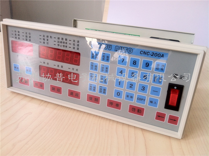
Step key
<Step setting>: Used to enter the data setting state.
<Start Step>: Used to set the memory to start positioning.
<End Step>: Used to set the end point of the memory.
Production volume
<Production setting>: Used to set the target production amount.
number key
<0>...<9>: A total of 10 keys are used to input numerical values, among which the “0” key is used at high speed in the winding machine for high and low speed switching>.
Display switch button
<Speed>: The speed "RPM" and the output display are switched.
<Return to zero>: The output counter is cleared to zero.
Function key
<Auto>: Auto/No Auto Switch button.
<Brake>: When parking, the bobbin brakes or relaxes.
<jumping segment>: When the winding is paused, skip to the next position.
<Retraction>: When the winding is paused, jump to the previous position.
<Reset>: In any state, the current operation is terminated and returned to the standby state.
<Parking>: When the winding is completed, the current operating procedures are suspended.
<Startup>: Start the winding action.
Data display light
<Starting point>: The starting position of the cable rod. This position is the distance calculated from the origin of the cable rod.
<Width>: When the copper wire is wound around the skeleton (bobbin), the skeleton needs to be wound.
<Line diameter>: diameter of copper wire (need to calculate the thickness of the lacquer bag), setting range: 0-9.999mm.
<Total number of turns>: Number of turns required for winding, setting range: 0-99999.9 laps or 0-99999 laps.
<Winning and jogging>: To prevent the phenomenon of slipping, disconnection, etc. due to high speed during winding, the number of turns of slow winding after starting, setting range: 0-999.9 laps.
<Stop Slow>: To prevent the phenomenon of slipping, disconnection and counting inaccuracy due to high speed when stopping winding, the number of turns of slow winding after high speed to low speed before the number of windings is completed. Range: 0-999.9 laps.
<High speed>: The speed (rpm) at high speed winding, the percentage of the maximum speed is displayed on the display, and the setting range is 10%-99%.
<Low speed>: The speed (rpm) at low speed winding, the display shows the percentage of the maximum speed, the setting range: 6-10% "If the low speed is set too low, the device cannot start.
Data key
<Data Selection>: Used to select data items when editing.
<Line direction>: Used to set the direction of the line in the inner or outer line when editing the cable.
<winding direction>: Used to set the clockwise or counterclockwise direction of the winding of the bobbin during editing.
<Parking at both ends>: When editing, it is used to set whether the cable bar is to be stopped at both ends of the bobbin.
<Auto homing>: When editing, it is used to set whether the cable lever is automatically displaced to the winding position of the next product.
<Auto Start>: When editing, it is used to set whether to automatically start the second product after completing a product.
<Alternative>: It is mainly used to set the direction of the cable, the direction of the winding, stop at both ends, automatically return to the position, and automatically start.
〈←〉: When editing, use to move the cable lever to the left and set the winding point.
〈→〉: When editing, use to move the cable lever to the right and set the winding point.
Status display light
Standby: Lights up—indicating standby, lights are off—indicating winding or editing.
Operation: Lights up—indicating that the winding is in the light, the light is not lit—indicating that it is stopped.
Slow: The light is on—it indicates that the wire is being wound at a low speed, and the light is not lit—it indicates that the wire is being wound at a high speed.
Positioning: Lights on—Indicating that the cable rod is positioned as a wrap or returned to the origin.
Overspeed: The light is on—the winding speed is too fast, and the cable bar is out of sync with the bobbin.
Connection: Lights up - indicates that the network communication is busy.
Speed: Lights up—Indicates the speed displayed on the current Output/Speed display.
Yield: Lights up—represents the current display of the Yield/Speed display.
Finish: Lights on - indicating that the production quantity has reached the production target
We provide One year warranty
Note: Weight and shipping costs vary widely due to different product specifications. Please ask the customer for the weight and shipping cost before purchasing. We will tell you the shipping price according to the actual weight and country. Never deceive customers. Please understand!
Thank you!
payment method:
- We accept the following payment methods:
-Lending, VISA card, bank bank wire transfer, Western Union and so on.
Global quick sell on the payment -All deal Alipay.
Shipping:
- Please pay attention to your order address must fill your shipping address match. (If you are from Russia, please leave your full name, which is very important)
-Items will be paid within 3 business days after payment.
Delivery will be available worldwide via Epacket / China Post Airmail / UPS / FEDEX / DHL / EMS.
The -otdalenny area may cause additional shipping costs.
- Please check the details of the delivery, in case of damage, please accept it and contact us immediately. We confirm and send you a new one
Guarantee:
-defektnye problem must be delivered within 7 working days after delivery of goods;
-Damage goods must be submitted within 5 business days after delivery.
contact us:
- If you want to order a large order wholesale, please do not hesitate to contact us.
- If you need to order multiple items, please let us know first. We can offer you a discount.
Feedback:
Any comments from you will be highly appreciated. If you are satisfied with our service or product, please give us a 5 zvezd. If you have any questions, please contact us and we will give you as soon as possible.

0 Comments